Thursday, December 26, 2013

Korg sp-250 repair: no sound on outputs


This Korg came to me with no output sound. Looking around the around the power amp IC, I could see the standby/mute function (pin 5) was not going high, as it is supposed to. I was able to trace the trace back to Transistor 4, which did not ring out as a transistor should. Suspecting that the transistor was the fault, I searched for a replacement or a cross, and found that the transistor is actually a DTC114ESA, known as a "digital transistor". I had not encountered one of these before, but found that it is actually a regular NPN transistor with the biasing resistors built in. It is called "digital" because it is biased to be used as a switch, as an inverting switch. It saves the designer from having to bias the transistor externally with resistors.
 
From its datasheet, here is a description of the circuit:
\
And here is how it appears in the schematic for the SP-250:


And finally, here is where it sits in the circuit board:


It is useful to add that the keyboard works and sounds fine with this transistor removed. By removing the transistor, you cause the mute rail on the power amp IC to go high right away. You may get a bit of a "pop" when turning on the keyboard though, so it is better to have it installed. However, a handy way to test whether you are having a problem with this transistor (or somewhere upstream in the standby circuit) would be to pull it out and see if the keyboard starts working again.

Tuesday, October 15, 2013

Korg Triton Touch Screen Replacement


This Korg Triton came to me with a broken touch screen. The touch screen, or "digitizer" is attached right to the lcd screen, and sits right above it. On this Triton, the digitizer did not work but the LCD was clear and in good condition. A new screen, available here, costs $250.00. This part includes the LCD as well as the digitizer. Replacement digitizers are available on ebay for 50.00 or so, so we went that rout, intending to attach the digitizer to the existing LCD.

The part that arrived looked a little different, but it was the right size. However the cable was smaller. Additionally, the cable is upside down (the conductive area of the pins is on the opposite side). Further, if you look at the picture of the original part, seen below, the pinout of the cable is slightly different. What would be pin 5 on the new screen was routed to pin 8 on the original part. See the picture below.

I was able to salvage a ribbon connector from a salvaged dvd player, and then go through the mental work of connecting the pins in the correct sequence with jumper wires to the korg circuit board. If you don't have a salvagable ribbon connector, I am sure you can find one on Digikey or Mouser, as long as the spacing is correct for the ribbon cable on the new digitzer.

 Routing the wires from the ribbon connector to the Triton circuit board takes some brain work, but I was able to achieve this, and it works perfectly. I routed pins 1 -4 from the digitzer to the same pins on the Korg Triton circuit board.  Pin 5 from the new digitizer goes to pin 8 on the Triton (that's the first one that crosses over.  Pin 6 from the new digitzer then goes to pin 5 on the internal connector, 7 goes to pin 6, 8 goes to pin 7, and if you did it right pin 8 on the Triton is already attached to pin 5 coming from the new digitizer.

This worked, I would recommend not giving up if you don't get it right. Double check your pinout or see if you need to completely reverse the pinout you tried. Don't physically attach the digitizer to the LCD before you are sure it works right, too.

Why not? In my case, I was scratching my head because the X and Y axises seemed to both be reversed on the new touch screen... if moved my touch more to the left, the touch would register more to the right..Ditto for up and down I realized that, rather than fooling around more with re routing pins, this problem was solved by turning the digitizer around 180 degrees. I was glad I hadn't attached the digitizer o the LCD with the double sided tape yet.

Finally, after that I found that the new screen had to be calibrated. The very top areas of the touch screen didn't work. Worse, I couldn't access the calibration feature in the korg because this requires access to the upper right area of the touch screen to accomplish.

Performing a reset does not reset the calibration (enter+o).

However, entering the internal test mode does erase the calibration data... so I was able to do so by doing that. The test mode is entered by pressing 0 + 4 while turning the power on. That info is available in the service manual, which can be googled and downloaded for free.

Finally, since I had done the reset, I had to reload all the factory sounds. I did this using my  floppy emulator drive. These seem to work with the Triton, but you have to play around with the jumper settings, and for me it only worked if I first let the triton format the drive, then put it in the computer and loaded the factory sounds, then moved it back to the Triton.

SO, if you are in a position where you have a replacement digitizer that has the wrong size cable, don't give up, but be prepared for an ordeal, or send it to here Offbeat Electronics and we will do it for you.
The Original Ribbon Cable rerouts some of the pins. This is not done on the replacement.

The original triton digitzer has a wider cable.


Monday, October 14, 2013

Alesis DMPRO repair

Alesis DMpro


 This unit had no outputs when it came to our shop. The issue with these Alesis drum machines is that the filter capacitors fail, and some of the other electrolytics. I believe it is because they are really small.... that's why I always recap the whole unit with higher voltage capacitors, and if they are a little bigger I move them a little bit as shown in the picture below. A small bit of hot glue holds them in place, and they last much longer than the original ones.

Midas Verona Soundboard


At Offbeatelectronics.com, we repair soundboards and mixers as well as keyboards and synths. We do on-site work as necessary, and assure the quality of our work with an excellent warranty.

This particular mixer resides at the Jubilee Fellowship Church in South Denver; an excellent place. This repair was performed on site, due to its large size.

Don't forget a torx screwdriver when taking this thing apart! 

The main issues were the necessity for a thorough cleaning, and deoxidizing. Other issues were the result of some loose ribbon cables between boards, and the most serious issues were broken TRS jacks on the outputs and inputs. On many of the insert jacks, the tip connector was broken off, making the inserts appear to be malfunctioning. It seems that the 1/4" jacks are prone to freeze to the tips of the plugs, and the jacks break when the cable is pulled out.

This unit was in excellent condition after we performed the repair.

These jacks were the culprits in many issues with the soundboard

Roland KR650 repair: bad electrolytic capacitors


This particular model suffers from leaky electrolytic capacitors on the main board. By leaky, I don't mean electrically; I mean there is some nasty liquid leaking out of these things! The result is all kinds of distortion in the outputs, low volume, intermittent problems, etc.

I have repaired a few of these. The repair has always been permanent, however on most instances the liquid that leaks from the capacitors burns through traces on the board. On this one, the liquid burnt out the V- supply to one of the op amps near the DAC chips.


So, the repair consisted of removing all the surface mount electrolytics on the main board, cleaning up all the liquid, replacing the caps, and repairing a trace that supplies the V- to one of the op amps near the DACs.  Other traces may be damaged too, so if it still doesn't work when you replace the caps you will have to check the traces that run near them.

I used standard through hole caps instead of surface mount on this job. I bent the leads and attached them to the pads; there is plenty of room for this, and I applied a bit of hot glue on the leads to hold them in place. If my memory serves, they were all 3.3 and 10uF caps.


The instrument sound great now. I also replaced all the tact buttons. There sure are a lot of buttons on that thing!


Finally, the contacts on this one were good. However, I think this was a transitional model, and the key contacts are no longer available. This may be a consideration in judging the cost effectiveness of repairing this model; if the contacts show signs of failing, it would be worth trying to repair them first (perhaps by recoating them) before investing time and money in fixing the other issues.

The highlighted area is where I found destroyed traces, supplying the V- to one of the SMT op amps near the DACS
.

Thursday, August 1, 2013

Yamaha DX7 repair : no sound, new battery, loading patches


This dx-7 suffered from no output volume. The solution involved replacing the relay which comes just upstream of the outputs (both phones and mains). . It's main purpose is to disconnect the outputs during power up and power down, so that there is no annoying "pop".

For testing purposes I removed the relay and connected the outputs with the little jumper wire you see in the photograph; this enabled me to make sure my diagnosis was correct, and that the keyboard worked with the relay bypassed. It then continued to work once I put a new relay in.

A photograph of the mainboard with the relay removed and bypassed is shown below.


Relays seem to be a common point of failure in older gear, especially audio equipment. I have found bad relays in casios as well.... in fact the muting circuits in many keyboards, primarily in place to eliminate the popping sound present when turning the unit on and off... are in general prone to failure and should be inspected. Other newer keyboards use fets to shunt the outputs to ground, and these fets sometimes go bad and cause distortion or clipped volume.

I recently worked on and RD300 which used fets for this purpose.. they had started to fail and caused clipping and distortion on the outputs, and a considerable loss of volume. I removed them and it sounded like a brand new keyboard.

Anyway, I also put a new battery in the DX7, as well as a socket to make future battery replacement easier (see below).

 Loading the presets is possible through midi, but there are a number of steps you have to go to on the DX7 to get it ready to receive midi sysex messages. The info here is useful.


Sunday, June 2, 2013

Another Farfisa Problem : hum in outputs, reverb tank, and bass tones

For those of you wondering how the bass tones are developed on your Farfisa compact (the black notes), they are simply the lowest octave notes sent through a filter. What I mean is, there is not another divider on the oscillator cards for those lowest octaves, those notes are just the same ones as the lowest octave but are routed through a filter before being sent to the outputs.The card with the filter is shown here:

The signal goes into that card from the contacts for the bass notes, and comes out and is routed to the output.

Another note:

 The old high voltage capacitors shown in this picture, below, were completely dead in a unit I recently worked on, and this added a lot of hum to the outputs. These caps need to be high voltage because they filter the power to the tube pre-amp. Apparently the Farfisa used this style preamp because they wanted it to work with their pizo-electric reverb tank, which is discussed on this blog .
This style of tank was used for reasons discussed here.

Since the tank was completely destroyed in the unit I was working on, I did manage to get a more traditional spring reverb tank working in the farfisa, but it required that I add a preamp in the circuit to drive it, not on the recovery side but on the driver side.I also replaced the rectifier, shown here. It is a more modern one and I was ultimately able to attach it to the inside of the chassis for the preamp.


Friday, May 31, 2013

PolyMoog Repair


This polymoog was one of the most challenging units I ever worked on. The circuit design is complicated and not at all intuitive or familiar. There are no circuit descriptions, and the flow chart could be pondered and studied for months, before the depths of its complexity could be plumbed .

 I never really believed those stories about technology being provided to us by alien beings, but the polymoog made me reconsider.

There were issues with stuck notes. This turned out to be relatively simple, the Polycom IC's, which are installed on little cards, were at fault in this instance. This was relatively easy to repair.This unit came to me with little repair cards, as shown below, so I was able to plug them in and fix this issue somewhat quickly.


These cards contain the polycom IC's, one per note. They create an envelope and mix the waveforms. The resistor values for the resistor shown in yellow change for various octaves up and down the piano.


Another issue was that all of the Bb's (except for the highest 2) of a certain waveshape (pulse or saw, I can't remember) were dead.

This was the result of a dead divider IC, shown below. Since these dividers divide down from the top note, and then go down from there, if one is dead everything below it will be dead as well.

This IC and it's neighbors divide down each of the notes and provide them to the polycom IC's. When one section of one IC goes bad, all the notes below it go bad too. Eg: all but the top 2 Bb's were silent on this keyboard.


Another issue was with the CD4007 IC's. These are used to control the preset voltages going to the VCF, resonators, and pretty much all of the various "top" boards. They are used to rout the particular CV's (generated through resistor networks) to those boards when the unit is in preset mode, or they rout the output of the various faders to ththe top boards when the unit is in variable mode. When they have burnt out, either the Variable mode of a control doesn't work, or the preset mode doesn't work. They are readily available from digikey.com and socketed so as to be easy to replaced. Note that each some are oriented with pin one facing upwards, and some are reversed!


Finally, issues with the VCF came down to bad transistors at the VCF current source (q11 and q12,) as well as some bad CA3080's throughout the VCF section.


When testing these CA3080s, remember that they have a very tiny range of input voltages (a volt and a half or so at max), and fairly low output voltage swings as well, so set your scope appropriately!


Zip tie repairs (!) : on a VK7 with crooked keys AND and an SY55

I don't frequently use zip ties in repairs, however I do believe they can be excellent and versatile tools. There are situations where an original part simply is not available, or cost effective. In those cases, with the customers approval, I have sometimes employed the zip tie with great success.

In this situation, I used a zip tie to secure the keys on an SY55: drilled a tiny hole through the key and used a zip tie to hold it to the chassis. The repair is permanent, sturdy, and the key behaves exactly the same as its neighbors.

notice the zip tie just visible on the Bb key

the other end of the zip tie is in a washer

On the VK7, the bushings tend to wear down, and the keys slide off. Buying new keys doesn't help much, and a new keybed can be pretty expensive. Zip ties between the keys work flawlessly at straightening the keys out, without adding any interference or resistance, and keep the keys on the bushings.. Plus, the metal casing around the keybed makes it impossible for the zip ties to fall off or move around. This is a great, permanent, and effective repair!


Juno 106 noisy chorus repair

I was able to repair crackling on the Juno 106 chorus by replacing all the tiny transistors (npn and pnp) on the jack/chorus board, as well as recalibrating the chorus section. The crackling occurred when bass heavy tones (especially chords) were played.

Some of the replacement transistors, although excellent substitutions electrically, needed to have their legs twisted since the pinouts were different.


K2000 Repair, LCD contrast capacitor added; similar to XP50 contrast issue


This Kurzweil primarily had an issue with the 220 uF capacitor right near the fet transistor  which regulated the 5 volt rail. That was causing the fet to heat up. Once that capacitor was replaced, there were still issues with the LCD contrast. Using the old trick of holding enter and turning the alpha wheel didn't really help; what ultimately fixed the issue was adding a 10 uF electrolytic capacitor between the LCD contrast voltage and ground (see photo). I found that this greatly stabilized the LCD and made the writing legible. Although there is a capacitor that is supposed to filter this voltage already, I couldn't easily find it, and adding another capacitor fixed the issue.
This was a situation where the customer did not want to spend too many resources on repairing the issue; so although this repair is not one" right out of the textbook" , it did fix the problem and the unit is working.


In my opinion, the idea of using the microcontroller and PWM to create a voltage for the LCD is a scheme which is prone to failure. When the user data containing the contrast parameter is lost or corrupted, or the PWM circuit for the LCD contrast fails (as it did here), the user is left with a blank screen. I think it is far more sensible to use a good old potentiometer to provide the LCD contrast voltage.

A similar issue occurs on the Roland XP50, another synth which uses the microprocessor to store the LCD contrast parameter. When you change the battery on an XP50, you may wind up with a blank screen In that case I used the info kindly listed here, which tells you how to ground the contrast pin in order to bypass the PWM controlled LCD contrast voltage.

Thursday, May 30, 2013

Jp8000 Repair: cracked circuit board


Sometimes an apparently tiny crack, like the one on the circuit board of this JP8000, can be a very insidious problem. I repaired this one with regular insulated, stranded, small gauge wires. The hardest part was going through each trace and locating good spots to solder the wires, and keeping everything in order. The board was restored to 100% functionality. It is good to note that on this particular keyboard, when a reset is done, the pitch wheel must be re calibrated: otherwise it will not work and the jp8000 will be out of tune


. .
The repaired circuit board

Sunday, March 24, 2013

Polivoks repair: dead outputs, 120 volt conversion, scaling issues

This unit came to me almost completely dead: neither oscillator working, just a power light and a slight hiss.

Bad paper and oil filter capacitors were the ultimate cause of the dead oscillators, but once they were replaced there were serious issues with the keyboard tracking.

At this point it became tricky since the only schematics that seem to be available are in Russian!

I made some headway by replacing the op-amps on the keyboard circuit board. I used a reference table found here,

Russian Ref
Europa/USA Ref
Function
KR140UD8B uA740 , uA741, LF351,... Single standart AOP
KR140UD12 uA776, MC1776, LM4250,NTE888 Programmable low power AOP
KT315G 2N3904A NPN transistor

which states that the russian op amps cross with uA741's, which are super standard monolithic op amps.

This fixed many issues, however, there was a gradual detuning of every note if the sustain was turned up.

With no circuit descriptions (that were in English), I was ultimately able to use the international language of schematics to find the sample and hold circuit on that keyboard circuit board. It consists of a fet, and an op amp and a few capacitors. Essentially, while the key is depressed the voltage flows through the fet and charges the .22 capacitors. Then the key is let up, the fet opens up and the capacitor remains charged to the same voltage, and continues to flow through the op amp (a7 on the schematic below). Since the op amp has super high impedance, the capacitor discharges so slowly that it holds at the same voltage for a long time, and the op amp output stays at the sampled voltage for quite a while. A good description is available here.

The sample and hold circuit thus demands a fet based op amp, so that it doesn't draw too much current from the capacitor and cause the sample voltage to decay too quickly. The 741 op amp worked perfectly everywhere else as a pin for pin substitution for the russian op amp, but not in this sample and hold circuit!  I replaced it with an original russian one, and everything worked fine. (I am sure I could have replaced it with any fet based op amp, but I had russian ones left over since I had replaced quite a few on this circuit board, having use a shotgun approach.)

Interestingly, here is a website which shows a sample and hold circuit using the 741... notice the addition of the 10k resistor, which probably helps the 741 work without drawing too much from the capacitor. 

Here is a picture of the circuit in question


Once all this was settled, the keyboard worked well. I installed the mods located here for external CV and Gate, and I also swapped out the transformer with one that can convert 120 volts down to the 34 volts, center tapped, that the polivoks needs for power (thus you can run it off from regular wall power). I installed an IEC connector and it is all set!


Wednesday, February 20, 2013

Rheem Mark VII Organ Repair


This gorgeous instrument would shut down unpredictably, or sometimes there would be excessive distortion on the outputs. My first suspicions were with broken solder joints, or perhaps failing electrolytic caps in the power section or on a circuit board. Sure enough, over time, I was able to detect low voltages from the power supply, as well as some AC on the DC rails. I replaced the filter capacitors, the rectifier, however the problem still persisted. This was an unregulated power supply,so there wasn't that much to replace or check.

I then disconnected,  board by board, each of the various circuit boards from the power supply, to see which area was loading it down, but there seemed to be no particular issue with any of the different rails.

This was a real mystery, until I decided, finally, to check the resistance across the terminals of the power switch. Although the switch was working mechanically...opening and closing as it should, there was a 30 - 70 ohm resistance across the contacts of the switch even when the unit was turned on.

I was able to disassemble the switch, and spray it with some cleaner and used my new fiberglass cleaning brush to clean the contacts, and all was fine. It has not usually been my experience that AC power switches can fail in that manner, but after 30 years or so of service, I suppose anything can fail.


Thursday, January 31, 2013

OBERHEIM TVS-1 DIGITAL KEYBOARD AND SEM REPAIR


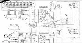
Although the schematics are easily found for the TVS-1, an actual circuit description of the digital keyboard circuitry is hard to locate. Having just fixed issues with this circuitry in two separate synthesizers, I decided to write my own.  In case anyone else is crazy enough to delve into this and sort it all out, this could be useful information, even if incomplete.


There are four purposes to the digital keyboard circuitry: one is to provide the correct  control voltage "cv", a voltage which will produce the correct frequency oscillation in the SEM module(pitch), the second produce is the "gate" voltage, a voltage which tells the SEM card that it is in use... enabling it to produce sound. The third purpose is to activate the sem cards in the right sequence (in unison, or right first and then left, etc). The fourth purpose is to astonish and stymie the repair technician with a brilliant, yet complex, array of logic gates.

The circuitry is designed to process two note polyphony, so after holding down one note, any second note played is sent to the other sem module.

This circuitry uses CMOS chips with a supply voltage of 9 volts... unlike many later logic chips (TTL) which only work with up to 5 volts.

1) the heartbeat of the circuit is A8, which is designed to produce a clock pulse which drives the other logic gates. It uses some RC components and a 4001 logic "or" gate. It's output, labeled "clock", should like like a clean square wave.

2)this "clock"  pulse is routed to A8, a "counter" device which sequentially routes pulses among 6 outputs, labelled "a1 -a6".

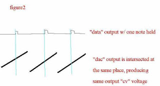
3) These signals (a1-a6) from A8 are routed through a1, then the keyboard, then a2, which essentially produces a type of serial output which contains information about which keys were pressed. This output is shown in figure 1... it essentially is a serial synchronous data signal, which produces voltage spikes which reflect which of the 37 keys were pressed. Ultimately, these spikes lines up with the "dac" signal, and depending where the spike falls along the dac signal, an analog voltage is produced for EACH key that is pressed, these voltages are higher if the higher keys are pressed. Note that the voltage spikes are recurring, synchronous with the DAC signal, and thus line up in the same spot each time with with the recurrent dac signal, as long as the key is held. See figure 2.

4)Now the beauty of the design can be seen... an analog voltage for EACH key can be produced, and by manipulating the "dac" signal, you can make that voltage be higher or lower, or if necessary you can curve the dac signal slightly making the voltage difference across the keyboard non-linear.


5)the "dac" signal is produced using the outputs "a1-a6", by Ic's a16 and a17, and a series of resistors making a voltage "ladder"... an old fashioned "dac". The signal,when all is right, should be a 3 volt sawtooth as seen in figure 1 and 2. Conveniently, the signal can be modulated up and down by 3 volts by using the transpose switches, and adjusted using the trimmers on the board. The length of one "DAC" wave corresponds exactly to the time period of the output on the "data" rail.

6)It is useful to note here that any issues in the circuitry described thus far will produce intonation problems for BOTH left and right voices.... issues with the "clock" signal, the "dac" signal, or with the circuitry used to produce the "data" signal.
Most of the next section addresses the circuitry that effects each voice seperately.


7) "LGate and Rgate are signals which are either high or low, low signalling the "gate is open", and the voice is in use.

8) "RTAKEN and LTAKEN are signals which go High when the right or left voice is taken.

----
When a key is pressed on the keyboard, a voltage spike is present on the "data" signal. Let us suppose that left voice first is selected. In this case, A11 pin 12 and 13 will be high, allowing  pin 11 to go low.

9) A12 pin 13 can now go High, which represents a clock pulse to latch A6.

10) The whole purpose of A6 and the network around it, is to "record" the position of the data pulse at that  time of the key press, and to repeat it each DAC signal. A6 takes that recording when a12 pin 13 goes high, which moves the clock on the latch. After that, at each  point when data lines a1-a6 are in that position, the network of logic gates a5,7,9, 8 and 11 will create a pulse which should line with the dac signal in the right position, so that the correct CV is produced by A18 pin 2. This voltage is stabilized by the small cap, and then run through op amp A6, which does not produce a voltage gain, but a current gain.

11) The gate is opened (goes low) on the first press of a key when a12 pin 13 goeshigh, a14 pin 4 goes low, then a15 pin 10 goes high. This, when synchronized with a data pulse at A14, causes a14 pin 12 to go low (and a14 pin 13 to go high. This happens at the first keypress, and initially opens the gate. After that, A15 pin 11 goes high with each successive DAC cycle,a15 pin 4 goes low, and a15pin 10 goes high.  and as long as there is a concurrent data pulse at 14 pin 9 (ie the key is held down), L gate stays open, and a sound is played from the left SEM. when the key is let up, the data pulse is no longer present at pin 9, and the gate is allowed to go high again. now a11 pin 13 is high, and the process can start again.

The process is essentially mirrored on the circuitry which corresponds to the Right Gate.


========================

Some other things:

Some issues with a weak resonance effect in the VCO's came down to a weak 3080, a transconductance op amp.

The customer was also concerned about driving the sequencer with an external clock,which did not produce the correct voltage for the TVS logic... for example a standard TTL square wave, from a 5 volt clock,  may not drive the TVS CMOS logic chips properly.These chips are designed to see logic highs above 7 volts (see http://www.allaboutcircuits.com/vol_4/chpt_3/10.html). Thus in the signal path between an external clock jack which I installed,   I added the small circuit below, which was effective in buffering the external clock input, and allowing it to accept a wide range of voltages. The second transistor is added to make the output square wave in phase with the input (as the first stage turns it upside down). The high value collector resistors mean that the circuit wont draw much current... you may notice it is not a wonderfully designed amplifier circuit, and more biasing could be done... however the transistors are either off or completely saturated, so I think all that extra biasing would be unnecessary.