Saturday, December 20, 2014

Oberhiem TVS-1 Sequencer Tuning Issues: sequencer scaling issues


The Sequencer on the TVS 1 can get out of tune (not scale correctly). There are several areas to check... foremost you can check that the 14v voltage created by the 723 regulator on the sequencer is correct... failures could be around the 1% resistors, the filter capacitors, or the chip itself. Oxidation on the pins that connect the boards together could also be a culprit... the voltages have to be pretty exact for the unit to scale correctly.

Another issue could be with the DAC voltage... it is worth checking it with a scope to make sure it rises smoothly and over the full range of voltage.

The trim pot will also only get you so far... although it is for this purpose, in this case it was too far out of tune for the trim pot to correct the issue.

In the case of this particular unit, the issue was with the capacitors shown highlighted in the image below... these polyester capacitors had started to fail and lost their ability to hold the voltage they are required to hold (it's a type of Sample and HOLD circuit they are involved in). They are charged to a certain voltage with each DAC cycle and they must hold that voltage until the next DAC cycle (which comes pretty quickly).  That voltage becomes the CV for the SEMs, so it is important that it is exact (as a mere 10th of a volt significantly changes the pitch. They leak different amounts of voltage for different CV values... hence the scaling issues.

Replacing those capacitors brought the scaling back 100%.

Another interesting point is that you can move the connector (coming out of the sequencer) from the A connector to the I connector, and bypass the quantized voltages coming from the A connector, and just get the analog voltages directly from the pots themselves. You would have to be more careful in adjusting the tuning pots on the sequencer, but you could bypass this problem, and also use this move as a test to see if the analog portion of the sequencer was working correctly.


Juno 60:Dead notes, distortion.


This Juno 60 came in with a bunch of weird key scanning issues; some notes didn't work some that did were distorted. It was clear that the issues were more serious than dirty contacts, so after briefly looking at them I started probing with the scope on the data lines. Finally I found that the VCC for IC 52 & 53 was low (about 3 volts when 5 volts is expected). Although I initially thought that it was simply a broken trace, on careful inspection of the schematic I noticed that those chips have a separate VCC, produced by OP amp IC 51. The 15 volt rail is voltage divided down to 5 volts at the input to this op amp, and the resulting 5 volts coming out on pin 7 is used as the VCC for these chips... which serve as a DAC for the KCV (filter control voltage).
It turned out the real issue was with capacitor 128... it was leaking and dragging down the voltage at that voltage divider. This caused the KCV (filter control voltage) to come out at 3 volts instead of 5, and caused distortion coming through the filters.
It is rare to see a ceramic capacitor fail, but clearly with an older instrument like this components that are usually reliable can ultimately go bad.

In red are the OP amp VCC supply for the filter DAC

Here is where it is located on the actual PCB.

Wednesday, October 8, 2014

Understanding the Tape Backup Scheme in a Jupiter, Programming an arduino to save and load backup data to a Jupiter 6 and save it to an SD card!


The Jupiter 6, like many other synthesizers of its generation, was made to backup its patch settings onto an audio cassette recorder.

The patch settings exist inside the Jupiter as a sequence of 1's and 0's. To accomplish the task of getting those digits into a cassette, the Jupiter is designed to create a waveform, with a frequency in the audio range, and then send it via audio to a cassette recorder, which is designed to record audio waveforms.

The waveform consists simply of long and short pulses. The Jupiter converts its 1's to long pulses, and it's 0's to short pulses. It then plays them, sequentially, as a pulse wave form, which the cassette recorder can pick up.

It's like morse code... the combination of long and short pulses.

When you restore from the cassette backup, you play the waveform back to the Jupiter, which detects long and short pulses, and then stores them in memory as 1's and 0's again, after a bit of error checking. There are about 20,000 such pulses in the 6 seconds of backup, so the procedure happens really quickly.

On the Jupiter, The pulse lengths of a long pulse are 500uS, and the pulse length of a short pulse lasts 125 uS. uS stands for microseconds, of which there are 1 million in a second... meaning that a "long" pulse is perhaps a bit of a misnomer. For example, it takes light about 5 Usecs to travel a mile... so light itself could only go about 100 miles in the duration of a "long" pulse.


From the photo above, (taken from the Jupiter service manual, it is also obvious that a digital "1" could be comprised of a pulse that lasts for 500 uSec at 0 volts, or a pulse that lasts for 500 uSec at 5 volts.... it is not the amplitude or phase of the pulse that determine its digital value, but simply the duration.

Below is an audio recording, from audacity (a great free audio recording application for windows or Linux), of a real Jupiter 6 backup. I zoomed in considerably so that the individual pulses can be seen. Remember that these are going by really fast, you will get about 20,000 of these in pulses 5 seconds, so the view below is zoomed in considerably.


Reading from left to write, at the first y axis crossing, we have a digital 1, then 0,0,1,0,1,0,1,0,1,0,0,0.
We are just reading the time between zero crossings, we don't care if the pulse is above or below the x axis.

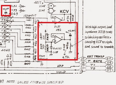
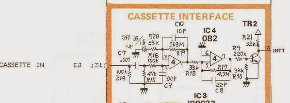
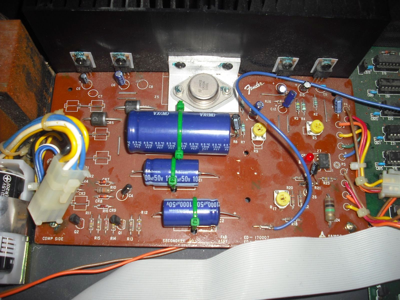
You will notice that the pulses shown are somewhat rounded and not nice and square. This is because this is the audio version, so in order to get to nice square waves from these rounded ones, when they are sent into the tape load jack,  the Jupiter uses the circuit below to convert the wave into square pulses that can be easily timed digitally.


This circuit comprises an op amp and some capacitors to achieve nice square pulses. It works from left to write and ultimately sends the data to pin 13 of the CPU (intel 8051). This is an interrupt pin on the processor, and when in tape Load mode, the processor times the microseconds between the pulses, determines if each is a 0 or a 1,  and stores the data in RAM bit by bit.

The data on the audio recording all starts with a "leader tone", a series of 1's (500 usec pulses) that lasts for a few seconds. Not much is needed, but the Jupiter uses this to recognize that data is coming.


In this project, I used an Arduino UNO to digitally record the data coming in on pin 13 of the microprocessor, and timed each individual pulse. I was then able to establish a threshold to determine which pulses were short and long. I was able to store that binary data on an SD card, and I was then able to play it back directly to the microprocessor (at pin 13), and therefore load the sounds digitally (without the use of the audio recording).

The purpose in doing this was so that I could clean up an unusable backup. Apparently, on the backup, some of the short pulses were not short enough, so that they were confused with long pulses. This created issues with reading the backup into the microprocessor. By recording the pulselength of each individual pulse, I was able to play around with the threshold between long and short pulses and consequently restore the backup to the Jupiter 6 digitally.

Below is the setup and coding I used to achieve this; it consists of an arduino Uno (a programmable microprocessor), an SD card reader (to store the data), and an extra 32k of ram on a breakout board that I had to construct as a buffer to store the data (couldn't record it to the SD card directly, it comes in too fast!).

The Arduino is shown in the middle, the add-on SD reader to the right, and on the left is the SPI ram breakout board I constructed.

One would think that the modern SD card is super fast, however it is made to store bigger chunks of data at a time... so I needed a buffer to cache the data as it came in from the backup. Once the backup process is complete, I could then write the data to the SD card for storage and manipulation.

To achieve the necessary buffering on the Arduino, I added  32k of SPI RAM using an 8 pin DIP chip 23K256 mounted on a perfboard (above left). Some code which contains some nice workable subroutines for accessing memory in RAM is located here. One obstacle which I had to overcome was that the chip I was using is a 3.3 volt chip, and the Arduino uses 5 volt TTL logic levels. Going from the chip to the arduino was fine (a 3.3 volt "high" is high enough to register as "high" on the 5 volt arduino, however to get signals from the Arduino to the chip I had to employ voltage dividers. I used 3 equal value (220 ohm)  resistors in series on each of those lines, connecting the 5 volt input to one end of the voltage divider and ground to the other. I then got my 3.3 volt output from between the 1st and 2nd resistors. It therefore dropped the level from 5 volts to 3.3, which is easy to do with 3 equal resistors since 3.3 is 2/3 of 5. I used 220 ohm resistors. There is a good discussion of this topic here. It is important to use values of resistors low enough to preserve the integrity of the signal, it seems higher resistances above 1k or so can distort the signals.

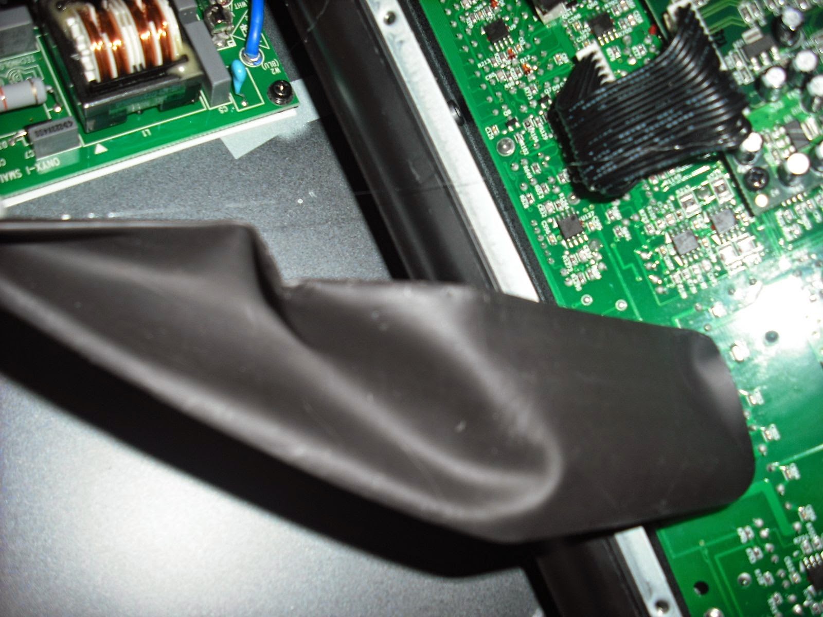
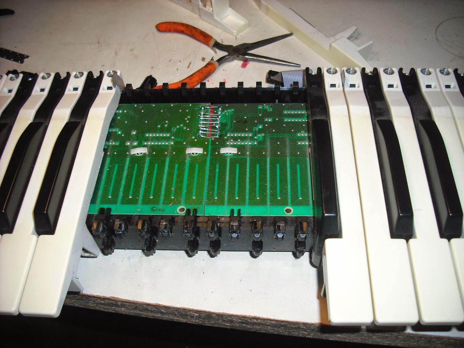
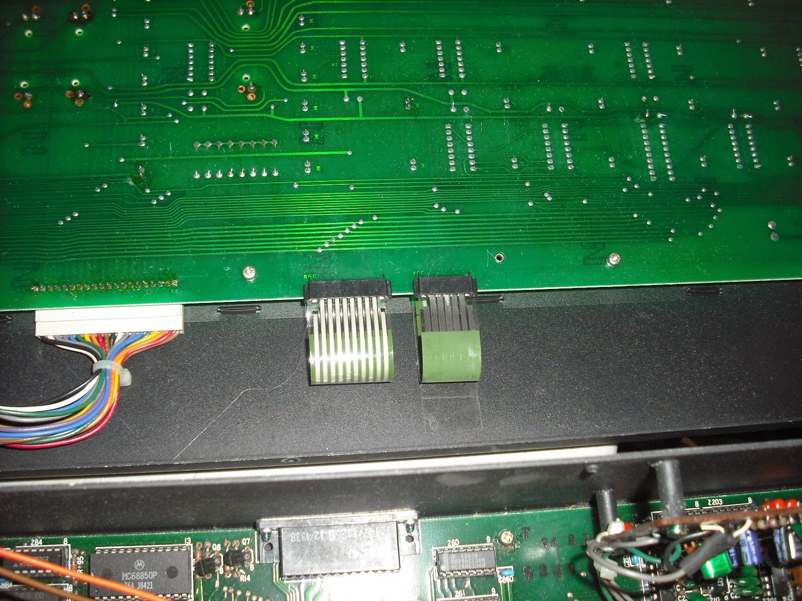
The next step was to physically attach an input pin on the arduino to the signal coming from the Jupiter... that is, to pin 13 of the microprocessor. This is because I wanted to have the signal pass, first, through the circuitry which converts the signal into a square wave. I had already assured that these components were working.

I tapped pin 13 on the 8051 processor to record the pulselengths as they came in. I used the same pin to send them back. A humble 4 wire phone cable did the trick of connecting the processor to the ardunio.


Next I routed that data to a pin on the Ardunio which I configured as an input pin.

The code I wrote to record, manipulate, and ultimately play back the data, is all below at the bottom of the page. The recording loop consists of a pair of "while" loops, one for a high pulse and one for a low pulse. Each one continually records the length of time the pin has been in its current state until the pulse ends. The last time recorded in  each while loop can be considered the pulse length. (You will note I divided the pulselengths by 4. This reduced accuracy, but I needed to fit the pulselength into one byte of data due to the limitation of Ram I had available.

One of the more interesting things I learned in writing this portion of the code is to optimize it so that the busy work is done right after the pin state changes. This is because we have the most time at that point, and we can delay readings for a few microseconds while we write the data to ram, as we can be confident at that time that the pulse will last for a while. Accessing the serial ram does incur a slight delay, so that's why I wrote the pulselength for the previous pulse to the serial ram just after each new pulse had begun.
This code worked flawlessly (after a bunch of revisions), and at the end of the 6 seconds of recording I had a long list of 20000 or so pulselengths.

The next step was to arrange the data in a spreadsheet, and find out what a good threshold would be between long and short pulses.

I found a threshold vaule by assigning a number to each pulse, so that I could later reconstruct them in sequence, and then sorted the spreadsheet by pulselength ascending. I could then see that there were no pulses in a long range of data... so I found the median of this empty range and called it the threshold.

Next, was able to apply this threshold to my arduino program, and prepare a new series of 1's 0's, and simply play it back to the Jupiter 6 to the same pin I recorded it from.

This was accomplished by writing another section of arduino code. This code loaded all the 1's and 0's it plans to write into Ram first, for faster access. It then writes a high pulse, and then pauses until the duration of the pulse comes up (500uS or 125 uS). It then writes the next pulse, and after writing it it figures out when to end it, and then writes that pulse. Once again, the code was arranged so all the calculations and RAM reads were done right after writing each pulse, when there is the most "free time".

It worked! I believe that it worked because my arduino was able to write super accurate pulselengths to the processor, and because I was able to determine a good threshold and then structure all the pulses accurately... the short ones were exactly 125 uS and the long ones exactly 500 uS.

All the code is below. It was written hurriedly... obviously if this was made for production there could be a lot of cleanup and optimization done. Also below is a small video of the procedure working... notice the lights going on and off, indicating a successful load!


=========================================
Arduino C++ code below:

//all includes HERE
#include
#include


//all Defines HERE
#define SRAM_DEVICE 5  // SRAM on pin 5
#define SRAM_READ  0b011  // Read data from memory array beginning at selected address
#define SRAM_WRITE 0b010  // Write data to memory array beginning at selected address
#define SRAM_RDSR  0b101  // Read STATUS register
#define SRAM_WRSR  0b001  // Write STATUS register
    // operation modes (status register)
#define SRAM_BYTE_MODE 0b00000000  // Byte mode (default operation)
#define SRAM_PAGE_MODE 0b10000000  // Page mode
#define SRAM_SEQN_MODE 0b01000000  // Sequential mode
#define SRAM_RSVD_MODE 0b11000000  // Reserved
#define SRAM_HOLD_MODE 0b00000001  // Set this bit to DISABLE hold mode

//all global variables HERE
char strValue[5];
int incoming = 0;

void setup(){Serial.begin(115200);
delay(1000);
pinMode(5,OUTPUT);// to set up ram
  pinMode(2,INPUT);//set up input pin
  SPI.begin ();
  sram_setup (SRAM_DEVICE);
 pinMode(10, OUTPUT);
 //noInterrupts();
 if (!SD.begin(4)) {
     Serial.println("initialization failed!");
     return;
   }
 }
void loop(){
 Serial.println("***********************************");
 Serial.println ("Welcome to Pulse R/W application!");
 Serial.println (".....");
 Serial.println ("Select an option:");
 Serial.println ("001... Read Pulse Code");
 Serial.println ("002... Translate raw.txt to bin.txt");
 Serial.println ("003... Write bin.txt to device");
 Serial.println ("004... Read BIN to RAM");
 Serial.println ("005... Read RAW to RAM");
 Serial.println ("006... Write a 1 or 0 to RAM");
 Serial.println ("Enter a choice!");
while (Serial.available()>0){
 
    for (int index = 0; index < 4; index++){
    char ch = Serial.read();
      strValue[index] = (ch);}} // add the ASCII character to the string;
   
  
    strValue[4] = '/0';        // terminate the string with a 0
    incoming = atoi(strValue);  // use atoi to convert the string to an in
   
 Serial.println(incoming);
 if (incoming == 1){recorder();}
 if (incoming == 2){translator();}
 if (incoming == 3){writer();}
 if (incoming == 4){readBINtoRAM();}
 if (incoming == 5){readRAWtoRAM();}
 if (incoming == 6){write1ToRAM();}
 Serial.read();
 while(Serial.available()==0){};
  }
  //++++++++++++++++++++++++++++++++++++++++++++++++++++++++++++++++++++++++++++++++++++++
    // do the recording and write to xRAM 0-28000
  void recorder(){
    countdown();


  byte pulseLength =0;//variable to store pulse length
  long i = 0;//variable to define RAM address to write to START AT 0!!!
  boolean currentPinState = 1; 
  while (digitalRead(2) == 0){}//pause until data has started
 
  unsigned long initMicros = micros();
  //*********************************************************************
  //RECORDING LOOP

  for(i=0;i<28000 br="" i="">   
   // delayMicroseconds(350);
         while (currentPinState == 1){ //do this while the pin is high
        
           pulseLength = ((micros() - initMicros)/4); //this will keep writing the length of the pulse until the pin goes low,
          currentPinState = digitalRead(2); //checks if the pin is still high, if so, repeat this "while loop" and record a higher value of micros for length
          
           //currentPinState = 0;
                                    }
                
         initMicros = micros(); //if the above "while"  loop has stopped, the pin must be low, so record the micros at the beginning of the new 0 pulse
         sram_write (SRAM_DEVICE, i, &pulseLength, 1);//command to write to RAM at address i
         i = i+1; //increment the counter, so that the length of this pulse that just started (a zero pulse) will be recorded in the next position of the array
       
 
       //delayMicroseconds(350);
        while (currentPinState == 0){ //while the pin is in a low state
          pulseLength = ((micros() - initMicros)/4);//get the micros of the length of the low pulse, write it to the array
          currentPinState = digitalRead(2); // check the pin state again, and if it is still low, run the above while loop again, adding a higher and higher micros value each time
         
          //currentPinState = 1;
                                   } 
                                   initMicros = micros(); //get micros at beginning of 1 pulse which has just started
                                   sram_write (SRAM_DEVICE, i, &pulseLength, 1);//command to write to RAM at address i
       }
   
  dumpRAMtoSD();
  Serial.println("finished!");
return;  
  }
//******************************************************************************************************
  void sram_setup (const byte device)
{
  digitalWrite (device, LOW);   // select device
  SPI.transfer (SRAM_WRSR);
  SPI.transfer (SRAM_SEQN_MODE);
  digitalWrite (device, HIGH);  // deselect device
}  // end of sram_setup
//******************************************************************************************************
// write 'length' bytes from 'data' to device at address 'address'
void sram_write (const byte device, unsigned int address, byte * data, unsigned int length)
{
  if (length == 0)  // don't bother if nothing to do
    return;
  digitalWrite (device, LOW); 
  SPI.transfer (SRAM_WRITE);     // write mode
  SPI.transfer (address >> 8);   // high-order address byte
  SPI.transfer (address & 0xFF);   // low-order address byte
  for ( ; length ; --length)
    SPI.transfer (*data++);     // data byte
  digitalWrite (device, HIGH);  // deselect device
}  // end of sram_write
//+++++++++++++++++++++++++++++++++++++++++++++++++++++++++++++++++++++++++++++++++++++++++++++++++++++++++
// read 'length' bytes into 'data' to device from address 'address'
void sram_read (const byte device, unsigned int address, byte* data, unsigned int length)
{
  if (length == 0)  // don't bother if nothing to do
    return;
  digitalWrite (device, LOW);     // select device
  SPI.transfer (SRAM_READ);       // read mode
  SPI.transfer (address >> 8);    // high-order address byte
  SPI.transfer (address & 0xFF);  // low-order address byte
  for ( ; length ; --length)
    *data++ = SPI.transfer (0);     // data byte
  digitalWrite (device, HIGH);    // deselect device
}  // end of sram_read
//==========================================================================================================
void dumpRAMtoSD(){ //Reads all byte data in addresses 0 - 28000 and writes them to raw.txt on SD CARD
  //setup SD CARD
  pinMode(10, OUTPUT);
  byte pulseLength;
//  if (!SD.begin(4)) {
//     Serial.println("initialization failed!");
 //    return;
  //28000 }
  
  File dataFile = SD.open("raw.txt", FILE_WRITE);
  for (int i=0;i<28000 br="" i="">  sram_read (SRAM_DEVICE, i, &pulseLength, 1); //reads at address i and writes it to pulseLength.
  //Serial.println(pulseLength);
  dataFile.println(pulseLength);//****
delayMicroseconds(10);
Serial.println(pulseLength);}
  dataFile.close();
  Serial.println("completed!");
return;}
//========================================================================================================== 
void write1ToSd(){
byte pulselength = 1;
File dataFile = SD.open("bin.txt", FILE_WRITE);
for (int i=0; i<10 br="" i="">  dataFile.println(pulselength);
  dataFile.close();
  Serial.println("done, go to BED!");
  return;}}
//+++++++++++++++++++++++++++++++++++++++++++++++++++++++++++++++++++
void dumpRAMtoSD2(){ //Reads all byte data in addresses 0 - 28000 and writes them to raw.txt on SD CARD
  //setup SD CARD
  pinMode(10, OUTPUT);
  byte pulseLength;
  
  File dataFile = SD.open("bin.txt", FILE_WRITE);
  for (int i=0;i<28000 br="" i="">  sram_read (SRAM_DEVICE, i, &pulseLength, 1); //reads at address i and writes it to pulseLength.
  //Serial.println(pulseLength);
  dataFile.println(pulseLength);
delayMicroseconds(10);
}
  dataFile.close();
  Serial.println("completed!");
return;}
//============================================================================================================
 
void translator()
{
  int threshold = getInput();
    //setup SD CARD
  byte pulseLength;
  byte isLongPulse;
// convert pulselength data in RAM from raw to 1's and 0's
for(int i=0; i<28000 br="" i="">  sram_read(SRAM_DEVICE,i,&pulseLength,1);
  if  (pulseLength > threshold){isLongPulse = 1;}
  if  (pulseLength < threshold){isLongPulse = 0;}
  Serial.println(isLongPulse);
  sram_write(SRAM_DEVICE,i,&isLongPulse,1);
  }
  dumpRAMtoSD2();
  return;
}
  //++++++++++++++++++++++++++++++++++++++++++++++++++++++++++++++++++++++++++
  void countdown(){  Serial.println("Activated!");
   
    //delay 5 seconds
    Serial.println("Beginning in 5 seconds!!");
    delay(1000);
    Serial.println("4");
    delay(1000);
    Serial.println("3");
    delay(1000);
    Serial.println("2");
    delay(1000);
    Serial.println("1");
    delay(1000);
    return;}
//============================================================================
void writer(){
  long leaderCycles = 3000;//about 1000 per second
  long initmicros = 0; //micros at pin change
  long currentmicros = 0; //micros count
  int pulseLength = 0; //the length of the pulse to generate
  byte longpulse = 0; //if this is a long pulse, then it will be 1, else 0
  long pulseEndTime = 0;
  pinMode(2,OUTPUT);
  countdown();
  //generate leaderTones
  for (long i=0; i < leaderCycles; i++){
    digitalWrite(2,HIGH);
    delayMicroseconds(500);
    digitalWrite(2,LOW);
    delayMicroseconds(500);}
  //leader tone finished
  digitalWrite(2,HIGH);
 pulseEndTime = micros();//get micros right at start of this loop
 
  for (int x =0; x < 28000; x++){
     digitalWrite(2,HIGH);
     sram_read (SRAM_DEVICE, x, &longpulse, 1);
     if (longpulse){pulseLength = 500;}
     else{pulseLength = 125;}
     pulseEndTime = (pulseEndTime + pulseLength);//get the time to stop the hight pulse
         while (micros()    
     digitalWrite(2,LOW);//start low pulse
     x++; //increment counter
     sram_read (SRAM_DEVICE, x, &longpulse, 1);
     if (longpulse){pulseLength = 500;}
     else{pulseLength = 125;}
     pulseEndTime = (pulseEndTime + pulseLength);//get the time to stop the current LOW pulse, the length of time of the pulse + the time the last pulse ended
           while (micros()  }
  Serial.println("COMPLETED!");
  return;
}
    
//+++++++++++++++++++++++++++++++++++++++++++++++++++


int getInput()
 {char StringIN[4];
  int incoming2 = 1234;
  Serial.println("Enter threshold");

 while(!Serial.available()) ;
 while (Serial.available()>0){
 
   for (int index = 0; index < 4; index++){
   char ch = Serial.read();
   delay(100);
     StringIN[index] = ch; // add the ASCII character to the string
     }}
      StringIN[4] = '/0';        // terminate the string with a 0
    incoming2 = atoi(StringIN);  // use atoi to convert the string to an in
   
 Serial.println(incoming2);
 Serial.flush();
 int threshold = incoming2;
    return(incoming2);}
   
 //++++++++++++++++++++++++++++++++++++++++++++++++++++++
 void readBINtoRAM(){
   pinMode(10, OUTPUT);
  byte pulseLength;
  
  File dataFile = SD.open("BIN.TXT", FILE_READ);
  for (int q=0;q<28000 br="" q="">  
    pulseLength = (dataFile.read()-'0');
    dataFile.read();
    dataFile.read();//get rid of the 2 line break characters
 // if (fileByte == '/n'){i--;}
 Serial.println(pulseLength);
  //put fileByte into ram at address i,
sram_write (SRAM_DEVICE, q, &pulseLength,1);}
Serial.println("COMPLETED!");
dataFile.close();
return;}
//+++++++++++++++++++++++++++++++++++++++++++++++++++++++++++++++++++
 void readRAWtoRAM(){
   pinMode(10, OUTPUT);
  byte pulseLength;
  
  File dataFile = SD.open("RAW.TXT", FILE_READ);
  for (int q=0;q<28000 br="" q="">  
    pulseLength = (dataFile.read());
    dataFile.read();
   //what I need to do is read the first, second, and (possibly 3rd chars until I get to line break and the other thing
   //then combine those 3 or 4 into an integer, and then convert that integer into one byte.
 Serial.write(pulseLength);
  //put fileByte into ram at address i,
sram_write (SRAM_DEVICE, q, &pulseLength,1);}
dataFile.close();
Serial.println("COMPLETED!");
return;}
//+++++++++++++++++++++++++++++++++++++++++++++++++++++++++++++++++
void write1ToRAM(){
  int address = (getInput());
  byte oneByte = 1;
  byte readByte = 0;
  SPI.begin();
  sram_setup(SRAM_DEVICE);
  sram_write(SRAM_DEVICE,address,&oneByte,1);
  Serial.println("completed. The data at position ");
  Serial.println(address);
  Serial.println("is now...");
  delayMicroseconds(1000);
  sram_read(SRAM_DEVICE,address,&readByte,1);
  Serial.println(readByte);
  return;}


Sunday, August 3, 2014

Kurzweil K250 with burnt out Power Supply Board


The K250 was a truly advanced instrument for its time. Stevie Wonder had a hand in designing it; and the original sticker price back in the 1980's was over 10,000 dollars... more than a brand new car.
 
A look at one of the four boards in the rack mount version will show you the incredible amount of circuitry and sheer number of microchips employed in making a true landmark instrument:


This particular unit came to us with a malfunctioning power supply. On it is a type of switching power supply, with several transformers, even some surface mount work mixed in... in short it seemed that the fastest point to a successful restoration would involve just replacing the power supply PCB rather than repairing it on the component level. Although I rarely replace circuit boards, the RT65-C available from JAMECO provided all the required voltages, and enough amps to power this beast. Additionally, it provides overload and thermal protection. After installing this little beauty in there and tapping the voltages to the right wires, it worked very well. I used the original screw type connector terminals mounted on a PCB, which I covered in tape to avoid any unwanted connections. I secured the replacement power supply with screws in the same place as the original, and also added a copper strap for extra security, and  a little bit of heat sinking. I tested it for several hours and it held up well. I put a bit of hot glue over the solder points on the back of the PCB, (the pcb which contains the terminals) to protect against the likely hood of the solder points breaking through the black electrical tape. Although perhaps better aesthetics could have been achieved in this mod, it is effective and secure.


Sunday, June 8, 2014

Mackie Pro FX 8 Mixer repair: weird noise in some channels, blown channels


This Mackie mixer came to me with a terrible and pronounced distortion on the outputs at all times, and also with several dead channels. On disassembly, I was able to find blown surface mount op amps, bulging coupling capacitors, and several dead transistors on the two dead channels.  Once these were repaired, the channels came back and the unit sounded fine...including the dead channels...

Until I put it back together completely (ie: placed the cover on the bottom and screwed it in)... as soon as I did that, the noise was right back!

Thinking maybe I had a loose connection or solder joint, I pulled the cover off and turned it on again. Now, the sound was clean as a whistle. I poked around on the circuit boards, trying to bend things, trying to find a failed connection, but everything was rock solid again.

But as soon as the cover was replaced and screwed in, the thing sounded terrible, and the same two channels failed.

I realized, after some thought, that the ribbon cable, shown below, which is encased in a black rubber sleeve, and comes from the power supply, presses down on some header pins on the FX circuit board (also shown below, header pins are in the blue square). The pressure is pretty intense when the cover is installed on the back (not a lot of extra romm in there). After time, those sharp pins had worked their way through the rubber sleeve and into the cable, and were making contact with the voltages coming from the power supply. They sent this voltage into various points in the signal path for the channels. This had made the noise, and eventually blown out those components on those channels.


This is clearly a design issue.

I cut those header pins down (obviously they are made for a connection which will never be used in this mixer), and then placed some hot glue over them, so that there is nothing sharp left to press into the ribbon cable.

This instantly fixed all issues, and fortunately none of the new components were destroyed in the brief time that I had the unit powered on in this condition.

The bottom line is, if you have a PRO FX8 which is starting to get noise all around, or in a few channels, this is very likely the culprit!

Saturday, June 7, 2014

Ensonic Post #2: keyboard calibration error on Ensonic VFX

Since my previous post is also dealing with Ensonics; I would mention here that the VFX keyboard will sometimes say "calibration error" while trying to turn on. In addition to the obvious checking of the cabling to the keybed, it may also be necessary to remove the keys in the middle of the keybed, and bypass the socketed connection between the two circuit boards beneath with jumper wires as shown below.

THis keybend uses metal plates moving on top of  sensors, creating an inductance, to measure velocity. It's a pretty neat scheme, unlike mostly all other touch sensitive keybeds which use rubber contacts. They are not as susceptible to dirt and dust.

On this particular keybed, some of those metal plates had to be glued back on to their respective keys; the customer had noticed that pressing hard on the keybed fixed the "calibration error" issue. However, over time and repeated pressings, he had dislodged the metal plates from the keys. Now that the jumper wires are soldered in place, he will no longer have to press on his keybed to get it to work!

Ensonic EPS disk drive Replacement with HXC floppy emulator, no sound output on EPS


This post will deal with the replacement of 2 floppy disk drives with SD card "floppy emulators"; devices which allow the substitution of an SD card (or USB memory stick) for a floppy disk

.Among the many models out there, I used the floppy drive emulators from HXC. These come with excellent documentation and support, unlike some other emulators I have purchased form EBAY. I was also able to ascertain beforehand that they work on the EPS.

To save on cost, I used the slim model (less bells and whistles), and ordered simply the circuit board, not the enclosure. This made it necessary to fabricate a mounting scheme from wood and a brass plate... the result was actually appealing and kept the job under 200.00 per keyboard, parts and labor included. For a better aesthetic appearance, the supplier also sells a fabricated enclosure which probably would make the repair look less like a mod. But in this case, we wanted to keep costs down.


Incidentally, I have also purchased standard floppy drives and retrofitted them to the EPS and other Ensonic Models; I documented that on a previous blog post . These units used the older "shugart" interface, and require some pins redirected when attaching a PC style floppy drive.

But floppy drives and disks are getting rarer and harder to find. In general, I avoid installing them nowadays, in favor of the emulators.

If you look up HXC floppy emulators on the internet, you will find all the information you need in terms of ordering one and setting it up. The trick is knowing how to create disk images from your floppy disks, and how to format and put them onto the SD card.

You need to install a special driver on the PC you are using to read from the floppy disk, not the standard windows floppy disk driver. You then need to use software to convert the disk to the HFE format. You then need to copy this HFE image file to your SD card, and rename it DSKA0000.HFE . or DSKA0001.HFE,,,, you can put tons of images on the SD card but they all have to be named sequentially starting at 0 with the convention I just illustrated (DSKAxxxx.hfe), and they all have to have the .hfe extension. You also need to have a .cfg file on the SD card, the right one for the EPS, at all times. You can only put the images on the root of the SD card, along with the cfg file.

But once you jump through all these hoops,  it truly works great in the end!


The only other issues with these EPS's was that the memory expander card needed to be removed, all the contacts cleaned, and then reseated. Issues with this card were causing there to be no sound output whatsoever on the unit.

Tuesday, May 20, 2014

Flat flexible cables: what to do when you encounter a broken one, or when you loose the little wedge that holds them in their socket:

Although often called a ribbon cable, this type of cable is actually an FFC, a flat flexible cable. Most of these cables are not unique, at least most of the ones I have encountered have an amount of contacts divisible by 10, and have either a .5 mm or 1 mm "pitch", which is the amount of space between the center of one contact to the center of the other.

They can be cut with a nice sharp pair of scissors, useful if you have encountered one where the end is a bit damaged, but may have enough conductive material left on it that you can fix it by just shortening it a bit. They can also be carefully cut vertically, if you have one that has too many wires ( is too wide).

On a few occasions I have received items for repair where the little wedge, that holds the ribbon cable into the socket, has been lost. That's a mistake I just don't make anymore... but many do.

I have had some success buying full replacement sockets from digikey and stealing the wedge (I think it's called a slide lock). The replacement sockets are not hard to find, as long as you have the correct number of contacts on the cable ends, and the right pitch, you may very likely find that exact socket for sale, and then use its wedge.

Of course, counting the number of contacts on the end of a tiny ribbon cable is kind of a pain.

When I have to do something like that, I take a nice digital picture of it, then blow it up on my computer screen, so I can slowly move my mouse over it and count out loud while I do it.


Sunday, May 18, 2014

Chroma Polaris Membrane Repair


While repairing a Chroma Polaris, I was forced to disconnect the ribbon connectors (technically FFC connectors) that connect the membrane to the panel PCB's. To my horror, even though I was being painstakingly gentle and slow, one of them tore, almost immediately, as soon as I tried to move it

Additionally,  the other 3 connectors -which didn't break as the first one did- still became cracked and intermittent when they were unbent from the position they had been resting in for 35 years.

In all cases, the cables broke where they had been bent... fairly close to the socket.

To repair the situation, I was able to cut the damaged portion off with scissors, and then grind away the insulating material (from the black side, not the silver side) with a wire brush attached to a dremel.


This may seem barbaric, but it actually worked flawlessly. ( I practice on the discarded portion of the ribbon cable first). You just need to buff it just enough so that you are able to ring through the traces on the ribon cable with your multimeter. If you buff it too much, you will grind through the conductive material, and render it useless. So you have to buff, and test, buff and test, until it rings through. It is naturally a good idea to practice first on the discarded portion of the ribbon cable.


On 3 of the connectors, I didn't have to shorten the cables too much, and they still stretched to their sockets


. On the 4th, I had to install a few wires and actually move the socket closer to the cable.

Either way, the repair has seemed to be permanent and hopefully the membrane will last another 30 years, especially if it is undisturbed. An additional step may be to recoat the exposed conductive part with conductive epoxy or paint; however it did not seem required in this situation.

One additional note: these flat ribbon cables are actually called FFC's, flat flexible cables. They are not called ribbon cables at all. Ribbon cables, technically, are made up of many insulated wires attached to each other. If these break, it is much easier to repair them. I am going to put up another post discussing FFC cables.

I also recapped the power supply and replaced a few faders.


AXIOM 49 with dead midi output


I posted this unit on the blog because it's failure was caused by a most unlikely culprit: a failed ceramic capacitor which was used to filter out noise on the midi output. Although I encounter countless failed aluminum capacitors, I rarely (if ever) have encountered a failed ceramic capacitor.

Nevertheless, this was the case here.

The unit came to me because the midi out was failing, it was completely dead. Of course I checked the jack and the connections around it, and all seemed fine. I reset the software.

Just for a lark, I removed the tiny small value capacitor that filtered the midi out line to ground, and found that the midi out came right back.

Although the capacitor did not read as shorted, it's capacitance must have drifted and increased significantly, enough to actually be filtering out the midi signal, rather than just noise.

It was a 220 PF cap, shown below, and the unit worked fine when it was removed, and continued to work fine when a new one was installed. The second picture shows the area where the cap was located... I believe labelled C4 on the silkscreen.


Sunday, April 6, 2014

Korg Triton LE Power Supply issues; heating up, distorted sound

This Triton came to me completely dead. The first thing I checked was the power supply, a 9v AC 3 amp wall supply with a 4 pin DIN connector... very much the same as some Alesis products... the DMPRO for example, which mentioned elsewhere in this blog.


I found a blown 2 amp inline fuse in the power supply, which can be disassembled (with the help of a drill). I am sure quite a few of these units have found their way to a trash can, with their only issue being this blown fuse. 2 amp fastblow and slow blow Pico fuses are available all over the internet.

After replacing the fuse, I turned the unit on, until to find that it was heating up, and only produced a horrid distorted tone.

I checked the voltage rails first, and noticed the 9 volt rail was substantially low. Through a process of elimination, and disconnecting one rail at a time, I came to find out that the 5 volt regulator had actually failed, and was sending excess voltage into the 5 volt rail, and consequently dragging down the other rails. It wasn't an extremely high voltage, at about 6 volts, and but it was enough to drag down the other rails.

This posed a substantial problem as this particular Korg uses a tiny surface mount switching regulator, and a tiny surface mount FET in conjunction with it. I found these parts in China, on ebay.


Once installed, the new regulator, fet, and a few caps (for good measure I replaced the filter capacitors around the regulator), the power rail came up and the unit turned on and worked. I also added a small 5.6 volt zener diode, which would short the rail to ground in case the voltage ever exceeds the specs again, in the hopes of protecting the chips.But this was too late...

Apparently, one of the PCM roms was damaged... probably by the previous over voltage, when the regulator first failed. There are four of these PCM roms on the Triton LE, and they provide the basis for all of the preset sounds and programs.

On this particular unit, after its resurrection,  some of the sounds, predominantly the organs and some brass sounds, sounded great. But others were distorted... primarily all of the piano patches and string patches. These must be looking for those damaged PCM samples.

Sadly, Korg no longer supplies these PCM roms, and so we had to settle for a partial repair, until such a time as I can scavenge these chips.

On the bright side, the sampling feature was restored, and many of the cool organ patches.. and probably about 50% of all the other patches sound perfect. But there was nowhere I could obtain those PCM roms.

However, if someone reading this has an old triton LE mainboard for sale, from which we could scavenge these chips, please let me know!


Saturday, April 5, 2014

Korg CX3- old style- with Leaky Electrolytics

Dual CX-3!


I am always skeptical when I receive these Cx3 organs for repair because of the known issues with the Seimens chips.. at the organ's heart are a couple of divide down oscillator chips that create the oscillations and gate them for each note. Their failure is a serious issue, because they are very hard to find and replace, and can only be replaced with other used chips that are probably very close to failure themselves. It seems someone was offering replacements, but apparently the supply dried up and I suppose they found it was no longer worth it to sell them.

But here was an instrument that didn't have that particular problem, rather it suffered from intermittent failures due to these badly leaking electrolytic capacitors seen below. The acid from inside of them ate through several traces on the boards, which had to be repaired.

The good news is that replacing them brought the keyboard back to life... the bad news is that there are about a thousand 10uF capacitors of this type sprinkled all throughout this keyboard. In this instance, due to financial and time constraints of the customer, we did replace only those that were seriously leaking... and left until later a full recapping, which is certainly necessary.

Currently the organ is working again, and sounding great, but most likely it will need some more caps replaced... unless the chips fail first!.

The failing capacitors were all 10 uF 16 volt capacitors. I doubt that it is coincidence... but it seems to me that the most frequent capacitors, in all gear, that I have to replace, are those rated 16 volts and less. I am not sure what is different between the processes used to make 16 volt caps and 35 and 50 volt capacitors, but I seem to rarely find failed 50 volt capacitors, unless they are too close to a heat source.

For this reason, I always use 50 volt capacitors, where possible, to replace them.


Friday, February 28, 2014

Jupiter 8 Replacement Faders and Buttons


For those of you looking for working replacement tact buttons for your Jupiter 8, they can be obtained cheaply, and brand new, from Digikey, digikey part number CKN9100-ND . Check them out. They are the same size, pin spacing, etc as the original. You just have to be really careful when you put them in the "actuators", the button caps, as they are called. You must do it slowly using an exacto knife to pry the old button out of the actuator, carefuly spreading the housing away from the button, and then carefully putting the new button into the housing. But it does come out just fine!


As far as replacement faders, these are a bit harder to find. This is not because they are unusual electrically (10k linear is about as common as you can get), it's because they come in such a large housing. One workaround is to disassemble the old fader, if it is beyond cleaning, and then install a new (smaller packaged)  fader into the old housing. If you get one with the right lever height, travel distance, etc, and mount it in the old housing, when you assemble the housing you essentially have a fader that feels great and looks and works exactly the same as the original.

I used part number
BOURNS PTA3043-2015CPB103
for my replacement fader. It is exactly the same electrically, travel wise, taper wise, and has the same lever as the Jupiter original. It is just in a smaller housing, which fortunately mounts perfectly in the Jupiter 8 faders original housing.

A picture is worth a thousand words... see below:

The replacement fader sits atop the PCB from the original fader

From underneath, you can see where tiny holes were drilled to connect the pins from the replacement fader to the pins from the original fader. Of course, I made sure the carbon was severed completely on the orginal fader PCB so as not to be adding a parallel resistance.
When the housing is installed, the fader looks original again, except now it works! From the top, the replacement fader is exactly the same as the original... exact same travel distance and electrical taper.


Tuesday, February 18, 2014

Prophet 600 repair; recoat contacts

Prophet 600


I recoated the contacts on this prophet 600 with the material shown in the image below. This stuff works great on all rubber contacts in keyboards... I have never had a problem with using it and never had a problem with it wearing off over time (although I have only used it for a few years). For contacts that are hard to find, such as the ones in this prophet, it is a great way to restore the functionality of all keys without spending too much money on tracking down parts.

One interesting note about the Prophet 600: it uses the same keybed as the Korg Poly 6. Yes, part for part it is the same keybed.

CircuitWorks keybad repair (bought from BD electronics)

 
In addition to the contacts, I recapped the power supply, replaced some pots, and replaced the battery. As far as the knobs (red!) I found these nice replacements from allelectronics.com . THe original unit was missing all its knobs, and it just didn't seem cost effective to track down 25 prophet replacement knobs.
 
These knobs are actually for 1/4" round shaft (the prophet uses 1/4" flatted shaft),but they have a set screw in each of them and can be attached easily and securely. The knobs also work with the 1/4" shafts modern cousin, the 6mm shaft, which is almost the same size but not quite.
 
Since the replacement pots I put on this unit had a 6mm shaft, the knobs were great in that they could be attached to both size shafts.


This is what a repaired contact looks like.


Sunday, February 2, 2014

Tips For Being A Successful Electronics Repair Technician

I have been doing this for a while now. Here are a few tips that I have found useful...if only I followed them more regularly....


1) Anticipate a harder, longer job than what you think. When giving estimates, aim high. I am not  a pessimist by nature, but this is just the way it is... almost every project and repair takes longer than predicted.

2) When things seem too puzzling, when getting frustrated, walk away, at least for a while. Put it away if you can, let it sit for a while. Fresh eyes can make all the difference. So can a bit of research, and a schematic... and a good night's sleep.

3)Some things are not worth fixing. The tough part is to know when to walk away.

4) Test everything BEFORE you start taking it apart, and note all flaws, notify the customer if you find additional things wrong, BEFORE you take it apart. This keeps you from getting blamed for those additional flaws... it's a lot easier to blame the tech for an issue once he has applied a screwdriver and poked round inside your electronic instrument!

5) Only put the repaired item back together enough so that you can safely test it, then test it before you assemble it the rest of the way. This saves the time of complete disassembly when the unit fails. Not only will you be upset to find out you still have problems with your repair, but you will have to take it all apart a second time!

6) Shake it before you put it back together, rather than hearing that screw rattling around inside when you are lifting it off of your bench, all reassembled, thinking it's all done.

7) Mark every connector that you remove with a sharpie, so you are not puzzled about what goes where. Mark the sides of hardware with a sharpie too so you can easily remember where they go when you reassemble. Every time you take something apart, remember you are (most likely) the guy that's going to be putting it back together, maybe weeks from now. Be nice to yourself!

8) finish every job as much as you can before walking away from it. Why have a bunch of half finished things lying around?

9) Keep the screws and hardware in baggies, separated enough so that you don't spend a bunch of time figuring what goes where.

10) start with a clean bench and workspace for every new repair. It's worth it.

11) If you can't find something in the shop, clean up as you look for it. This way, even if you don't find it, at least you wound up with a clean shop.

12)Don't call the customer with good news until you have tested it 100%, and it is 100% together. Otherwise, the customer may be on their way to pick it up and you will be scrambling to remember how to put it back together, or worse yet you might be scrambling to fix an issue you didn't fix completely.

13) Never lose your cool, with the repair or in interpersonal situations either. If a customer is being unreasonable, it is best to be like a professional politician and stay "on message", never getting sidetracked or emotional in a negative way.

KRK Rokit Studio Monitor Repair: distorition and pops on power on


This KRK speaker came to me with extreme distortion and popping on power on. Eventually I was able to narrow the issue down to the 4580 op amps used throughout the preamp circuit board. Not sure if there was an issue with the series of 4580's that were used in production of these "Rokit" studio monitors, but replacing the op amps made the problem go away, permanently. Each time I replaced one the problem improved; when they were all replaced it was gone!.

Below is a picture showing the effected 4580 op amps.

Technics sx-pr603 Digital Piano Repair: frequent lock ups, failure to turn on, intermittent problems and weirdness


This model of Technics Digital Piano (sx-pr603)  suffers from failing lead free solder around the IC's on the main board. Over time, the board heats and cools repeatedly and flexes, eventually cracking the microscopic connections between the surface mount IC's and the main board.

This causes lock ups, failure to turn on, and all kinds of strangeness with the unit.

It IS fixable, and we can fix them here at Offbeat Electronics, however be forewarned that the job generally costs about 250.00, and sometimes a few touch ups are necessary to keep the board running smoothly, in the first few weeks to a month or two after the repair (which are provided free of charge, of course). However, we have repaired these 100% of the time.

Repair consists of reflowing and adding solder around every one of the surface mount IC's. Also, I prefer to move the power transistors and related resistors off of that circuit board and to a separate heat sink, which I mount in the case.

I move them because I feel that the presence of those transistors and resistors introduces a tremendous amount of heat to the circuit board, and exacerbates the issues with the solder. Between reflowing the solder on that board, and removing the hot components from the board, full working order can be reached... I think this is a great sounding instrument, when it works, and worth preserving.